The synthesis and characterization of Poly (N-isopropylacrylamide-co-2,2,3,4,4,4-Hexafluorobutyl methacrylate) (PNF) nanogels
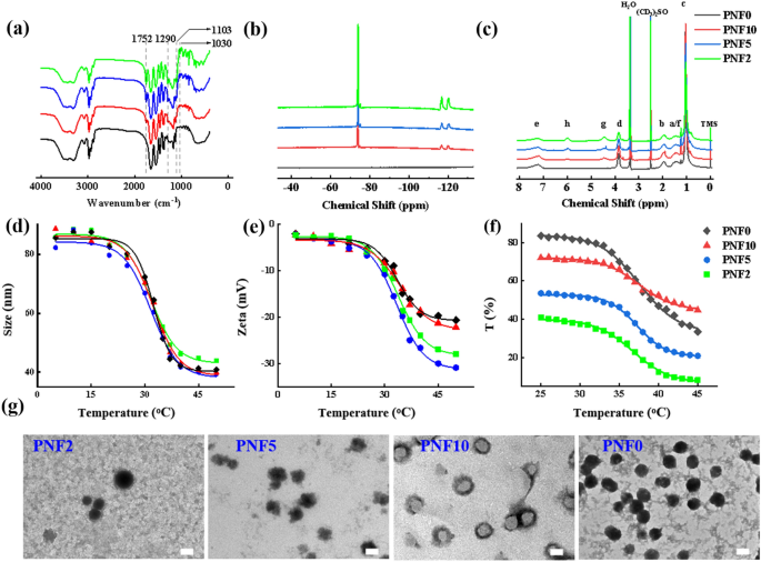
pNIPAM nanogels have been primarily polymerized utilizing 2,2,3,4,4,4-Hexafluorobutyl methacrylate (HFBMA) to enhance their affinity towards fluoroalkanes owing to their hydrophobic and lipophobic properties. Furthermore, PNF nanogels have been synthesized by the two-step seed emulsion polymerization methodology (Further file 1: Fig. S1) as per the synthesis components proven in Further file 1: Desk S1. Furthermore, the PNF nanogel construction may very well be altered by adjusting the addition order of response monomers. Nonetheless, pNIPAM nanogels, the core of PNF nanogels, have been initially synthesized by the first-step emulsion polymerization. Consequently, NIPAM conversions of roughly 95% have been noticed after a response for 30 min (Further file 1: Fig. S2). Consequently, HFBMA was added to kind the shell of linear pHFBMA. The PNF nanogel constructions have been regulated by the feeding ratio of monomers (NIPAM/HFBMA) and have been subsequently named PNF2 (2/1), PNF5 (5/1), PNF10 (10/1), and PNF0 (no HFBMA) in accordance with the feeding ratio, respectively. The chemical construction of PNF nanogels was characterised by NMR and FT-IR measurements. The absorption peaks of C = O (1752 cm–1) in -COOC- teams, C-F (1290 cm–1, 1103 cm–1, and 1030 cm–1) have been noticed within the FT-IR spectra of PNF10, PNF5, and PNF2 nanogels; nevertheless, enhanced absorption peaks have been perceived with elevated HFBMA utilization (Fig. 1a). Within the 9F-NMR and 1H-NMR spectra of PNF10, PNF5 and PNF2, the fluorine and hydrogen sign peaks (the peaks at a chemical shift of 4.5 and 6.0 ppm belong to -O-CH2– and -CHF-, respectively) have been noticed within the linear PHFBMA phase (Fig. 1b and c). The above outcomes indicated that the HFBMA monomers have been polymerized efficiently on the pNIPAM floor. Moreover, the molecular ratios of NIPAM and HFBMA and the HFBMA conversion price have been calculated conforming to the 1H-NMR outcomes via formulation 1. The molecular ratios of PNF10, PNF5, and PNF2 have been 16.7, 7.1, and a pair of.9, whereas their conversion charges have been 59.88%, 70.42%, and 68.97%, respectively. Thus, our findings have been much like the basic evaluation outcomes (Further file 1: Desk S2).
The hydrodynamic diameter, Zeta potential, and light-weight transmittance of PNF nanogel dispersions have been measured to detect their temperature-sensitive property (Fig. 1d–f). Nonetheless, the variation tendencies of PNF nanogels’ measurement have been comparable with rising temperatures. Though hydrodynamic diameters of PNF nanogels have been roughly 80 nm at 25 °C, they diminished to 45 nm at temperatures > 37 °C. The VPTTs of PNF2 (31.61 °C), PNF5 (31.65 °C), PNF10 (32.25 °C), and PNF0 (32.35 °C) diminished, thereby suggesting that the PNF nanogels’ VPTT decreased as HFBMA share elevated (Fig. 1d). Moreover, elevated temperature led to a rise within the particular floor space of PNF because of the nanogel’s contraction. Consequently, the PNF nanogel’s Zeta potential worth elevated and was thought-about secure. Notably, absolutely the values of the Zeta potential of PNF nanogels elevated because the HFBMA content material escalated owing to the sturdy electronegativity of the F atom (Fig. 1e). The LCSTs of PNF2 (36.48 °C), PNF5 (37.28 °C), PNF10 (37.49 °C) and PNF0 (37.59 °C) have been acquired after analyzing the sunshine transmittance information. Thus, the variation development of LCST was much like the abovementioned end result (Fig. 1f). It is perhaps as a result of the longer the linear PHFBMA, the extra hydrophobic PNF nanogels have been. Nonetheless, the hydrophobic PHFBMA didn’t have an effect on the VPTT and LCST of core–shell PNF nanogel dispersion. This discovering was opposite to our earlier conclusion that the hydrophobic items had an enormous affect on VPTT and LCST of random-homopolymer nanogels [33]. The TEM imaging displayed the core–shell constructions of PNF10, PNF5, and PNF2 (Fig. 1g). The above outcomes confirmed profitable synthesis of core–shell fluorinated nanogels. In any other case, PNF nanogels had wonderful temperature-sensitive properties.
A distinction agent, iohexol (240 mg I/mL), was administered earlier than x-ray imaging to disclose the passage of the fabric into blood vessels throughout subsequent animal experiments. The NaCl focus can have an effect on the polymer’s floor cost and its sol–gel part transition conduct in aqueous dispersions. Thus, NaCl was added to regulate the gelling conduct of PNF nanogel dispersion, whereas iohexol was administered to help within the injection of embolic supplies below the steering of DSA imaging. Our outcomes revealed that the dispersion with 0.5 wt.% NaCl may gel nicely at 37 °C temperature (Further file 1: Fig. S3).
Screening the formulation of TGFPE
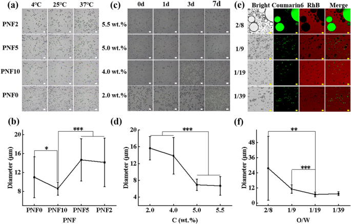
The impact of PNF nanogel composition on the soundness of TGFPE emulsion was investigated by stabilizing the TGFPE emulsion by PNF2, PNF5, PNF10, and PNF0 nanogels, respectively. The TGFPE emulsion modifications after fixed temperature remedy at 4 °C, 25 °C, and 37 °C have been noticed by optical microscope. It was noticed that the scale of emulsion droplets didn’t considerably differ below room temperature, however the droplets enlarged and their sizes elevated due to the coalescence after 37 °C remedy aside from the TGFPE group that was stabilized by PNF10 (Fig. 2a). A quantitative evaluation revealed that the imply measurement of TGFPE droplets stabilized by completely different PNF nanogels after remedy at 37 °C have been 14.15 ± 5.15 µm (PNF2), 16.69 ± 4.48 µm (PNF5), 8.58 ± 1.38 µm (PNF10) and 10.99 ± 4.32 µm (PNF0), respectively (Fig. 2b). Since TGFPE stabilized by PNF10 nanogels had smaller measurement and slender measurement droplets, the PNF10 was thought-about for stabilizing the final emulsion.
The screening of TGFPE fomulation. a The optical microscopic images of TGFPE stabilized by completely different PNF10 nanogels after treating at completely different temperature. b The statistical evaluation of droplets’ measurement in TGFPE. c The optical microscopic of TGFPE stabilized by PNF10 nanogel dispersion with completely different concentrasion at completely different factors of time. d The statistical evaluation of droplets’ measurement in TGFPE. e The fluorescent photographs of fluorescence labelled TGFPE with completely different ratios of aqueous part (5.5 wt.% PNF-RhB-10 dispersion) and oil part (HDFP labelled by Coumarin 6). f The statistical evaluation of droplets’ measurement in TGFPE. Scale = 20 μm, n = 20 for (a), (b) and (c)
We additional examined the affect of PNF10 focus on the soundness of TGFPE emulsions. After preliminary preparation, the TGFPE droplets stabilized by 2 wt.% PNF10 nanogel dispersion sank to the underside of the bottle, and their sizes have been the largest, thereby suggesting that the emulsion stabilized by 2 wt.% PNF10 nanogel dispersion had the worst stability. Furthermore, the TGFPE droplets stabilized by 4 wt.% and 5.0 wt.% PNF10 nanogel dispersion sank as a result of coalescence after making ready for two and 5 days, respectively. Nonetheless, the scale of droplets within the former situation enlarged as a result of coalescence, however the droplets within the latter didn’t differ considerably. Solely the TGFPE droplets stabilized by 5.5 wt.% PNF10 nanogel dispersion didn’t sink and enlarged concurrently after per week’s preparation (Fig. 2c and Further file 1: Fig. S4). A quantitative evaluation steered that the imply sizes of TGFPEs stabilized by PNF10 dispersions with completely different concentrations have been 14.84 ± 2.72 µm, 13.03 ± 4.36 µm, 6.95 ± 1.33 µm, and 6.66 ± 2.38 µm, respectively (Fig. 2d). To sum up, the soundness of TGFPE emulsions improved together with elevated focus of PNF10 nanogel dispersion. Nonetheless, the TGFPE emulsions didn’t simply deform in the event that they have been stabilized by larger concentrations of PNF10 nanogel dispersion, thus limiting their applicability (Further file 1: Fig. S5).
Apart from the above two points, the ratio of oil and aqueous phases (O/W) is among the most vital elements that have an effect on the soundness of emulsions. From the fluorescence-labeled TGFPE photographs, the sizes and distribution of droplets in TGFPE emulsions with completely different O/W have been in contrast (Fig. 2e and f). When the O/W was 2/8, the scale of TGFPE droplets was 27.63 ± 25.33 µm, suggesting {that a} secure emulsion couldn’t be achieved below this situation. With growing O/W of TGFPE, the scale of TGFPE droplets was calculated as 11.14 ± 3.32 µm of 1/9, 6.81 ± 1.88 µm of 1/19 and seven.39 ± 1.49 µm of 1/39, respectively. Furthermore, the scale distributions of TGFPE droplets have been uniform as O/W was 1/9, 1/19, and 1/39, respectively. The dimensions of TGFPE droplets having O/W of 1/9 was greater than the opposite two emulsions. By the fluorescence distribution area, we noticed that the oil part was surrounded by the water part as a disperse part, thereby suggesting that our emulsions have been of O/W kind.
We additionally perceived that the depth of fluorescence across the droplets emitted from rhodamine B (RhB) was stronger than different areas of TGFPE (Fig. 2e). This end result steered that PNF10 nanogels have been clustered on the two-phase interface, indicating that they efficiently functioned as stabilizers. Moreover, we noticed the TGFPE construction below TEM and observed that there was a circle with a darkish shade, thus proving our earlier conclusion (Further file 1: Fig. S6).
Part transition conduct and ultrasonic improvement efficiency of TGFPE in vitro
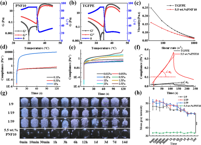
Rheological properties can be utilized to characterize the flexibility of embolic supplies for vascular embolization. With the intention to monitor the sol–gel state, the modulus of TGFPE emulsions and PNF10 nanogel dispersions, comprising storage and loss modulus, was measured below completely different temperatures from 25 to 45 °C. Because the temperature rose from 25 to 35 °C, their modulus decreased as a result of enhanced flowability. As temperature additional rose to 37 °C, their modulus elevated quickly. As their storage modulus was greater than the loss modulus, they transited to a gel state, and the corresponding temperature was named sol–gel part transition temperature (Fig. 3a and b). Moreover, the TGFPE emulsions, at completely different concentrations after gelling below 37 °C, resulted in an enhanced TGFPE complicated modulus because the focus of PNF10 nanogel dispersions elevated. This steered that the gelation energy of TGFPE may very well be strengthened by growing the PNF10 nanogel dispersion focus. Furthermore, the TGFPE emulsion at an O/W ratio of 1/19 had the next complicated modulus than different TGFPE emulsions with different O/W ratios (Further file 1: Fig. S7a). An evaluation of the viscosity of TGFPE emulsions below the identical circumstances revealed that the viscosity of TGFPE emulsions rose because the focus of PNF10 nanogel dispersions elevated. Thus, the soundness of TGFPE emulsions may very well be improved in the event that they have been stabilized by PNF10 nanogel dispersions with larger concentrations. The TGFPE having an O/W of 1/19 had the next modulus than others with completely different O/W and PNF10 nanogel dispersions, suggesting its larger stability and that the TGFPE emulsion viscosity rose because the ratio of O/W elevated (Further file 1: Fig. S7b–d). It was value noting that TGFPE had the next complicated modulus (124.8 Pa) than PNF10 dispersion (71.8 Pa) after gelling at 37 °C, suggesting that it had higher efficacy in blocking the bloodstream. We measured the TGFPE and PNF10 nanogel dispersion viscosities below completely different shear charges to detect their flowability, because the viscosity of embolic supplies vastly influenced the TAE process. A discount of three.68 folds was observed when the TGFPE viscosity decreased from 249.3 MPa.s below the shear price of 41.27 s–1 to 67.7 MPa.s below the shear price of 991.7 s–1. Concurrently, the viscosity of PNF10 nanogel dispersion decreased from 160 MPa.s below a shear price of 41.27 s–1 to 63.5 MPa.s below a shear price of 991.7 s–1 (Fig. 3c). Thus, it was steered that their flowability decreased because the shear charges rose, suggesting that each of them possessed the shear thinning property. Due to this property, the resistance was diminished once they have been pushed in vessels via the catheter, though they’d excessive viscosity when saved. After gelling at 37 °C, we discovered a speedy enhance in compliance occurring at 1 Pa and a pair of.5 Pa for PNF nanogel dispersions and TGFPE via the creep compliance checks, respectively (Fig. 3d and e). Thus, the end result that TGFPE resisted larger shear stress post-gelling than PNF10 dispersion confirmed that TGFPE had a stronger skill to withstand blood movement scouring. Moreover, the next TGFPE zero shear viscosity (6535.09 Pa.s) than PNF10 nanogel dispersion (398.41 Pa.s), indicated its larger mechanical energy after gelling (Fig. 3f). In conclusion, TGFPE has the potential of software in vascular embolization.
Characterizations of rheological and ultrasound imaging of TGFPE. The shear modulus at completely different temperature of a PNF10 nanogel dispersion and b TGFPE. c The comparation of shear viscosity at completely different shear price of PNF10 nanogel dispersion and TGFPE. Yield stress detection of d PNF10 nanogel dispersion and e TGFPE. f Creep and creep restoration testing of PNF10 nanogel dispersion and TGFPE. g Ultrasound imaging performances of TGFPE with completely different ratios of aqueous part and oil part and PNF10 nanogel dispersion. h The statistical evaluation of imply grey depth (n = 5)
The property of US imaging of TGFPE was measured to confirm whether or not it may very well be used as a US distinction agent. Thus, TGFPE had wonderful US imaging efficiency in comparison with PNF10 nanogel dispersions. Inside 2 weeks after gelling at 37 °C, we discovered that TGFPE teams may detect important US imaging indicators inside 2 weeks post-gelling and their depth was roughly ≥ 3 occasions than PNF nanogel dispersion (Fig. 3g and h). In keeping with the above outcomes, the TGFPE with an O/W of 1/19 and stabilized by 5.5 wt.% PNF10 nanogel dispersion was chosen for later experiments. The X-ray attenuation of TGFPE was measured by CT scan, and the CT worth was decided. When the proportion of Omnipaque elevated from 80 to 320 mg I/mL, the CT values of TGFPE elevated from 1810.31 to 3066.5. This confirmed that TGFPE exhibited the wonderful skill of X-ray attenuation (Further file 1: Fig. S8).
In vivo renal artery embolization and ultrasound imaging in regular rabbits
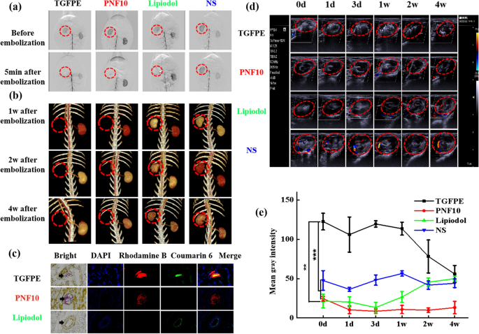
Renal artery embolization is often performed to guage the flexibility of embolic supplies for vascular embolization and US imaging efficiency preliminarily [34,35,36]. Underneath DSA imaging, a catheter was launched close to the doorway of the principle renal artery. After the passage of iohexol into the kidney, the TGFPE and PNF10 nanogel dispersions have been injected into the kidney vasculature. The kidney was not seen in DSA imaging after the injection of TGFPE and PNF10 nanogel dispersion for five min, suggesting the formation of a superb vascular embolization (Fig. 4a). Enhanced CT examination was additional performed to guage the revascularization of the kidney. As proven in Fig. 4b, considerable blood indicators have been detected within the kidneys of the NS group. The indicators weakened after vascular embolization by lipiodol as a result of its embolism properties, however they returned to regular ranges later owing to vascular recanalization. Inside 4 weeks after vascular embolization, blood movement indicators weren’t noticed within the kidney of TGFPE and PNF10 teams, suggesting that the vasculature was nonetheless blocked by the gel networks shaped by TGFPE or PNF nanogel dispersion. At some point after vascular embolization, kidneys embolized by fluorescently-labeled embolic supplies have been remoted and their slices have been noticed by fluorescence imaging. Furthermore, we discovered that the TGFPE emulsion and PNF10 nanogel dispersion remained intact within the vessel, whereas the fluorescence sign emitted from lipiodol was solely noticed on the blood vessel partitions (Fig. 4c). The kidneys have been remoted from the physique after vascular embolization for 4 weeks. Microscopically, the kidneys within the TGFPE and PNF teams shrank severely and have been necrosed, however the kidneys within the lipiodol group shrank mildly with none necrosis (Further file 1: Fig. S9a). Nonetheless, H&E staining revealed an absence of regular construction of renal slices within the TGFPE and PNF10 teams, whereas the kidney within the lipiodol group displayed a traditional construction (Further file 1: Fig. S9b).
Renal artery embolization and ultrasound imaging comparability of TGFPE, PNF10 dispersion, lipiodol and NS. a DSA photographs of kidney at completely different factors of time after vascular embolization with the TGFPE, PNF10 dispersion, lipiodol and NS. b 3D-CT photographs of kidney at completely different factors of time after vascular embolization with the TGFPE, PNF10 dispersion, lipiodol and NS. c Shiny area and fluorescence scanning of remoted embolized kidney slices inside 1 d after vascular embolization (arrow pointing to blood vessel). d Colour doppler and B-mode ultrasound photographs of kidney at completely different factors of time after being embolized by the above embolic materials or the injection of NS. e The statistical evaluation of B-mode ultrasound photographs in kidneys at completely different factors of time after being embolized by the above embolic materials or the injection of NS. The area surrounded by dotted purple line is the embolized kidney. **P < 0.01, ***P < 0.001
Enhanced Colour Doppler and B-mode US echo indicators have been detected within the TGFPE group kidney inside 4 weeks after vascular embolization, whereas US echo indicators have been weaker within the kidneys of different teams. 4 weeks post-vascular embolization, the echo depth of the TGFPE group was much like the NS and lipidol teams however nonetheless larger than the PNF10 group (Fig. 4d and Further file 1: Fig. S10). The imply grey worth of the TGFPE group’s blood vessels was the very best inside 4 weeks by the statistical evaluation of B-mode US photographs in kidneys at completely different intervals after being embolized by the TGFPE, PNF10 dispersion, lipiodol, and NS (Fig. 4e). The rationale for this is perhaps that TGFPE and PNF nanogel dispersion shaped a gel community for blocking the kidney’s blood provide completely, whereas lipiodol embolized the vasculature briefly. Moreover, we positioned the TGFPE-embolized kidneys and decided whether or not the embolic supplies have been nonetheless contained in the vessel on the embolization website by detecting considerably enhanced TGFPE indicators from the vasculature. Moreover, with shade doppler US, we noticed whether or not the vascular provide was recanalized or not. Given the above findings, TGFPE may very well be additional utilized in vascular embolization as a self-US imaging embolic materials.
Moreover, we additionally injected TGFPE and NS into the rabbit’s kidney below the steering of US imaging. Firstly, NS was injected into the kidney’s vascular provide. Nonetheless, we couldn’t observe the method of injecting these supplies. After injecting TGFPE, an elevated US imaging depth was noticed within the kidney (Further file 1: Fig. S11 and Further file 2: Video S1, Further file 3: Video S2). The movement and accumulation of TGFPE have been monitored below US imaging (Further file 3: Video S2). Therefore, it was confirmed that US imaging may very well be used for exactly guiding the TAE remedy, and TGFPE may very well be used as a particular embolic materials for profitable TAE remedy.
In vivo analysis of TAE and imaging efficacy in VX2 tumor-bearing rabbits
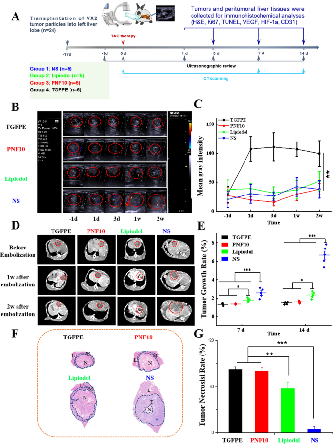
With the intention to consider the antitumor efficacy of embolization (Fig. 5a), 24 VX2-tumor-bearing rabbits have been randomly divided into 4 teams: NS, lipiodol, PNF10, and TGFPE. In contrast with a traditional liver space, the tumor space was coated by a chaotic vascular community below DSA imaging. Primarily based on this, tumors may very well be discovered simply, and we may inject embolic supplies into them exactly. After TGFPE, PNF10 nanogel dispersion and lipiodol have been injected into the tumor vasculature for five min. Nonetheless, the vascular community that was noticed earlier than its disappearance owing to the X-ray distinction agent couldn’t movement into it (Further file 1: Fig. S12), thus suggesting that the tumor vasculature was adequately embolized. Colour Doppler and B-mode US have been used to guage the tumor revascularization (Fig. 5b and c). Furthermore, a number of bloodstream indicators have been noticed close to the tumor within the management group, NS, throughout the entire experimental interval. The bloodstream indicators on the tumor weakened after embolization by lipiodol, however the indicators endured. In contrast with the above-mentioned outcomes, the blood movement indicators have been absent within the tumor’s vascular community inside 2 weeks after vascular embolization in shade doppler US imaging. This steered that the gel networks shaped by TGFPE and PNF10 nanogel dispersion weren’t nonetheless washed by the bloodstream and remained in vascular provide. Enhanced US-imaging depth from tumors within the TGFPE group was detected inside 2 weeks after vascular embolization below B-mode US, whereas in different teams, weakened echo indicators have been noticed within the tumor areas throughout the entire experimental interval. The development of tumor development was monitored by US imaging (Fig. 5b and Further file 1: Fig. S13). We additionally discovered that the tumor within the NS group enlarged considerably as time glided by, exhibiting a development of tumor development that was not inhibited fully. Though the expansion of tumors was inhibited because of the embolization impact of lipiodol, their sizes nonetheless elevated considerably 2 weeks after TAE remedy. Nonetheless, no important tumor enlargement may very well be discovered within the TGFPE and PNF 10 teams. With the intention to measure the scale of tumors precisely, the tumor development development was monitored by CT imaging (Fig. 5c). In contrast with the NS group, which confirmed a suppressed tumor development development, the expansion of tumors within the TGFPE, PNF10, and lipiodol teams have been all suppressed, after a 2-week TAE remedy. Furthermore, the tumor development charges within the TGFPE, PNF10, lipiodol, and NS teams have been 1.46 ± 0.14, 1.60 ± 0.13, 2.33 ± 0.26, and 6.65 ± 1.00 respectively, thereby suggesting that TGFPE and PNF10 nanogel dispersion displayed larger efficacy in suppressing tumor development than lipiodol after gelling in vivo (Fig. 5d). After a 2-week TAE remedy, tumors confirmed coagulative necrosis aside from tumors within the NS group whereas the tumors within the TGFPE and PNF10 teams confirmed full necrosis (Fig. 5f and Further file 1: Figs. S14, S15). In contrast with them, the lipiodol group tumors confirmed some energetic areas, suggesting that lipiodol couldn’t block the blood provide of tumors fully and that the lipiodol-induced vascular embolization recanalized simply. For measuring the tumor necrosis charges of all teams, tumor slices have been stained by H&E and scanned microscopically. An intergroup comparability revealed that the TGFPE (81.96% ± 3.48%) and PNF10 (80.96% ± 4.66%) teams had larger tumor necrosis charges than lipiodol (61.44% ± 8.37%) and NS (5.21% ± 3.33%) teams (Fig. 5g). To sum up, TGFPE displayed good efficacy for intratumoral vascular embolization and long-term US imaging steering.
Antitumor efficacies of TAE remedy and ultrasound imaging comparability of TGFPE, PNF10 dispersion, lipiodol and NS in VX2 tumor-bearing rabbits. a Schematic illustration of experiment schedule. b Colour doppler and B-mode ultrasonography photographs in tumors earlier than and at completely different factors of time after being embolized by the above embolic materials. The area surrounded by dotted purple line is the embolized kidney. c The statistical evaluation of B-mode ultrasound photographs. d CT photographs of tumors earlier than and at completely different factors of time after being embolized by the above embolic materials. The area surrounded by dotted purple line is the embolized tumor. e The statistical evaluation of tumor sizes at 1 day earlier than and after vascular embolization with the above embolic supplies or the injection of NS. f The H&E stainning of tumor after vascular embolization with the above embolic supplies for two weeks. (T) areas of tumor (L) liver tissue (N) areas of necrosis (M) tumor margins. g The statistical evaluation of tumor necrosis charges after vascular embolization with the above embolic supplies for two weeks. Scale = 2500 μm. n = 5, *P < 0.05, **P < 0.01, ***P < 0.001
The analysis of post-operative tumor microenvironment
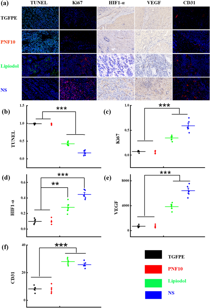
Embolization denotes the interruption of the blood movement to the tumors, thereby inducing ischaemic necrosis and tumor hypoxia. Though hypoxia is poisonous to most cancers cells, its exact results differ with its extent and period. Extreme and extended hypoxia induces cell dying, whereas gentle or short-term hypoxia may cause a number of adaptive genetic mobile alterations [34, 37]. The H&E-stained part revealed an in depth necrotic space, tumor structural disorganization, and some surviving tumor cells within the VX2 tumor handled with PNF10 and TGFPE. Nonetheless, many surviving tumor nidi have been present in tumors handled with NS and lipiodol (Further file 1: Fig. S15). Furthermore, TUNEL staining was carried out on tumor tissue sections, the place a rise within the inexperienced fluorescence indicated enhanced tumor cell dying within the remedy teams. An elevated degree of inexperienced fluorescence of TUNEL-positive nuclei was noticed solely in PNF10 and TGFPE-treated tissue sections, thus offering proof of apoptotic cell dying (Fig. 6a and b, and Further file 1: Fig. S16). Moreover, diminished tumor cell proliferation was evident from the decreased Ki67 expression within the PNF10 and TGFPE remedy teams in comparison with NS and lipiodol teams (Fig. 6a–c, and Further file 1: Fig. S17). The numerous variations in tumor apoptosis and proliferation indicated that PNF10 and TGFPE achieved full embolization of all ranges of tumor arteries in comparison with lipiodol and NS, thereby exhibiting a stronger antitumor impact.
Immunohistochemical evaluations on the neovascularization of VX2 tumor-bearing rabbits with numerous remedies on day 14 (NS, lipiodol, PNF10, TGFPE). a Confocal fluorescence microscopy photographs of TUNEL staining, Ki67 staining, HIF-1α staining, VEGF staining and CD31 staining within the residual tumor surrounding the tumor necrosis zone (authentic magnification, × 400). b, c, d, e, and f are a quantitative comparability of fluorescence intensities within the slices of TUNEL staining, Ki67 staining, HIF-1α staining, VEGF staining, and CD31 staining from plot A, respectively. **P < 0.01, ***P < 0.001
The native hypoxia induced by inadequate TAE remedy may cause activation of HIF-1α and enhancement of the VEGF expression. Consequently, optimistic HIF-1α staining was famous in each the cytoplasm and nuclei of viable tumor cells. Furthermore, HIF-1α-positive tumor cells have been positioned predominantly within the peripheral necrotic tumor areas [38,39,40]. In comparison with these with each NS and lipiodol therapies, HIF-1α, VEGF, and CD31 ranges within the rabbits distinctly decreased at 14 d with the remedies of PNF10 and TGFPE.
As proven in (Fig. 6a and c), HIF-1α expressions at 14 d within the PNF10 and TGFPE-treated teams have been a lot decrease than the teams handled with NS and lipiodol; thus, demonstrating important variations in HIF-1α expressions among the many 4 teams. Cytoplasmic VEGF expression was detected within the viable tumor cells on the periphery of necrotic tumor areas. Nonetheless, the variety of VEGF-positive cells considerably elevated within the NS and lipiodol teams in comparison with the PNF10 and TGFPE-treated group (Fig. 6a and d). Since microvessels have been heterogeneously distributed within the tumors, probably the most intense vascularization was noticed within the invading tumor margins. Moreover, CD31 expression considerably elevated on day 14 within the NS and lipiodol teams, whereas the CD31 expressions of PNF10 and TGFPE-treated teams considerably decreased (Fig. 6a–e and Further file 1: Fig. S18). In VX2 tumors, HIF-1α, in addition to CD31 expressions, confirmed a big optimistic correlation with VEGF-positive cells. The aim of embolization is to interrupt the tumor blood provide, thereby inducing ischaemic necrosis and tumor hypoxia. Though hypoxia is cytotoxic, the exact impact varies with its extent and period. Furthermore, extreme and extended hypoxia induces cell dying, whereas gentle or short-term hypoxia causes numerous adaptive genetic modifications in cells. Our outcomes concerning the HIF-1α, VEGF, and CD31 expressions indicated that PNF10 and TGFPE-treated teams successfully restricted neovascularization and collateral circulation when in comparison with NS and lipiodol teams.
The analysis of TGFPE’s biocompatibility
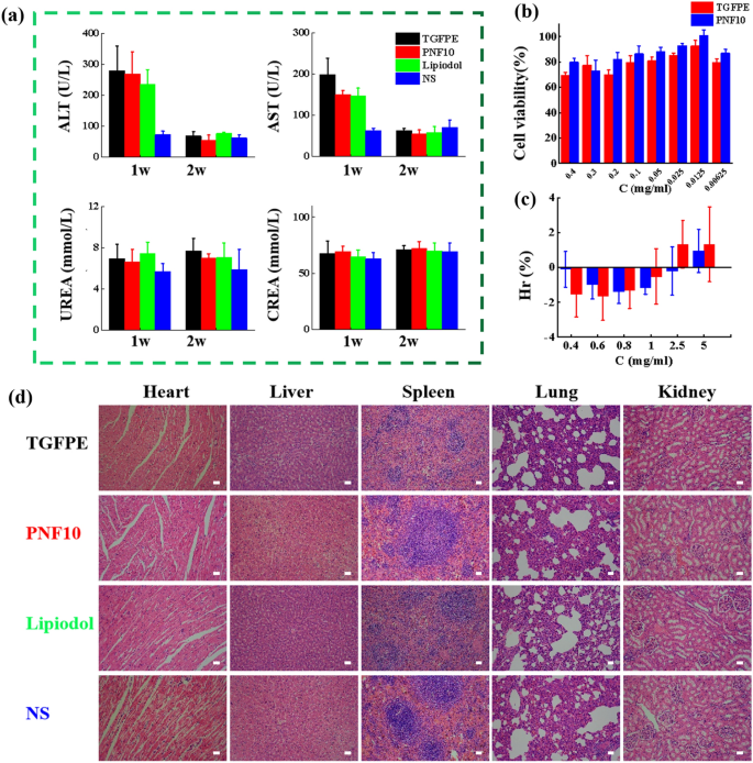
The biocompatibility of TGFPE was evaluated from a number of parameters like physique tissues, hepatorenal perform, hemolysis ratios (Hrs), and cytotoxicity. In our research, all serums have been used to detect the indexes of hepatorenal perform consisting of ALT, AST, UREA, and CREA. Though the ALT and AST ranges within the TGFPE, PNF10, and lipiodol teams have been larger than the NS group after TAE remedy for 1 week, all indexes returned to regular after a 2-week TAE remedy, suggesting that the hepatorenal perform of rabbits couldn’t be influenced via TAE remedy by utilizing TGFPE (Fig. 7a). The cell viability of TGFPE was > 70% when the focus vary of 0.00625–0.4 mg/mL was incubated with HUVEC cells for twenty-four h, indicating the low toxicity of TIPE (Fig. 7b). As proven in Fig. 7c, when the dilution focus of the TGFPE was 0.4–5 mg/mL, the hemolysis price was < 5% which steered good blood compatibility. After H&E staining was performed on regular organ slices from all of the teams, no apparent tissue harm and lesions have been noticed within the slices, suggesting that there have been no unfavorable impacts on regular organs after administering TAE remedy on rabbits by utilizing TGFPE, PNF10 dispersion, and lipiodol (Fig. 7d). Thus, we concluded that TGFPE had good biocompatibility.
Biocompatibility analysis. a Hepatorenal perform of VX2 tumor-bearing rabbits for 1 weeks and a pair of weeks after remedies: ALT (alanine aminotransferase), AST (aspartate aminotransferase), BUN (blood urea nitrogen), and CRE (creatinine), (n = 5). b Cytotoxicity comparability utilizing the CCK-8 methodology on HUVEC cells (n = 6). c Hemolysis comparability (n = 10) of TGFPE, PNF10. d H&E staining of the guts, liver, spleen, lung and kidney tissue sections of the experimental rabbits in every embolization group (Scale = 20 μm)

